


The CK12 Capsule Demystified
by Christoph Frank

Good day, fans of acoustic engineering and excellence in audio. This blog post is a slice of what will be a tradition at Austrian Audio. No, not Strudel but accessible science and straight-poop from our engineers.
What follows is an analysis & write-up of the 1954 patent for the venerable and rightly revered AKG CK12 capsule along with some revelation as to what made it a unique capsule. It is no wonder that practically everyone asserts a claim to having emulated this wonderful sounding classic.
All of this was done and delivered by Austrian Audio’s own Christoph Frank. He’s a Senior Acoustics Engineer, here at Vienna’s newest home of audio excellence, and is also Chief Weingruppen Selector on Free-Wine-Wednesdays at the canteen.
We now deliver a hot slice of his research to you. If you would like to read more of his writing and research, see his AES White Paper here.
Patent
The patent of the CK12 basically describes its advantage over the conventional dual capsule system described in the preceding Braunmuehl patent of 1935-1941.
The advantage is that the resistive portion for the gradient component of the capsule gets separated from the resistive portion for the pressure component by having a defined acoustic resistance between the two capsule halves. If your brain is already screaming “stop!”, don’t worry. The illustrations will make this rather clear.
In Braunmühl’s Version, the air-gap between membrane and electrode (yellow in Fig1. below) defined the resistance for both the pressure and cardioid component of the system and additional “Sacklöcher” [“blind holes” (in purple)] defining the pressure component primarily. This meant that it was hard to control the two components (basically the mixture between figure of eight and omni characteristics) independently and to achieve a consistent cardioid pattern.
The CK12 separated those two by using a slit (green) between the two capsule halves for control of the gradient component so it can be adjusted independently.

The result is a more consistent cardioid polar pattern that results in better polar pattern control when bringing the two capsule signals together.
Disassembly
The CK12 capsule is built up of two almost identical halves.
Each half consists of a membrane ring and an isolator, with the isolator containing the electrode and the resistance disk.
The membrane itself is glued to the membrane ring and has a resonance frequency of 800-1500Hz – both membrane material and resonance frequency varied a lot over the CK12s production.

Each membrane ring has 12 screws that hold it against the isolator.
Once these screws are removed, the membrane ring can be lifted – this can take some additional force because of the red coating on the isolation ring. This coating was “painted” onto the isolator as one of the last production steps and sealed the sub-assembly.
As can be seen below, the red liquid also entered the slits between membrane ring, distance ring and the isolator.
This red coating therefore provided additional sealing of the capsule against moisture and changes the appearance of the isolator ==> old CK12 capsules are also called the “Brass-Ring” version compared to the “plastic” version, as the newer C414 capsules are often called in the music industry.
In reality, the whole CK12 isolator is a big piece of solid plastic as well, but the dark red coating seems to make it look less “plastic” than the newer C414 capsules.

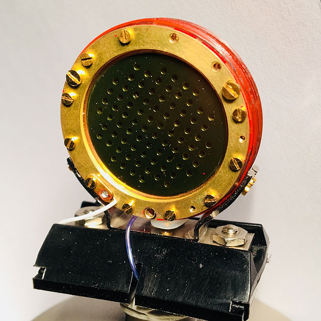
After removing the membrane ring and the isolating distance ring (30-50µm thickness), the electrode with its drilled holes becomes visible – it is pressed into the plastic isolator.
Besides providing isolation to make the capacitive function of the capsule work, the distance ring also defines the airgap between the membrane and the electrode. This has an influence on both frequency response and polar pattern of the capsule. This is due to providing an air suspension for the membrane movement.

The second critical influences upon frequency response and polar pattern are the resistance disks that can be found on the rear side of the electrodes.

The resistance disks are different for both halves in that the drilled holes are offset to form a path for the airflow through a slit formed between the two resistance disks. The slit is again defined by a distance ring of around 50µm although this was often customized at the factory for each microphone.
Important and interesting point: This distance has been observed to vary across units as this is a key factor in determining the quality, or characteristic of the cardioid polar pattern. The CK12 is known for its very consistent rear rejection of around 20dB. This required manual tuning for each individual capsule.
As the resistance disks are manually screwed into the electrode, the surface is “lapped” afterwards so as to ensure a smooth and even surface.
This lapping process is also done for the front side of each half and is very time consuming.

3D-simulations reveal the air volume inside the capsule from front electrode to back electrode – the air pressure is dramatically reduced in the slit formed between the resistance disks causing an acoustic resistance.

(3D simulation photo removed in order to prevent Engineering Team from giving Marketing Guy a beat-down [and a dis-invitation to ‘Free Wine Wednesday)
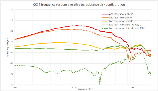
Resistance Variation
The acoustic resistance formed by the slit in between the two capsule halves is most critical for the frequency response and polar pattern of the microphone.
As shown in the graph below, the 0° frequency response for different configurations of the resistance disks is evident- from w/o disk (and therefore no acoustic resistance) to a critically tuned slit in between the two disks ==> this last configuration then also shows a good cardioid pattern with around 20dB rejection of sound sources from the rear (180°).